1 min read
Vertical Seal Troubleshooting On Your Continuous Motion VFFS Machine
The overall efficiency of any form, fill, seal machinery always hinges on the effectiveness of the sealing process. Packaging has many jobs to do-...
3 min read
 Christa Francis
:
Updated on July 23, 2020

 Deciding on an electrical conversion can take time and research. Typically, you’re interested in maintaining the ability to monitor and troubleshoot your VFFS machine, you may be having difficulty finding spare parts for your machine or you would like to use the machine in a different capacity. Knowing the process and planning for it is an important part of decreasing the downtime needed for this conversion to take place. This tech note focuses on the step-by-step procedures that occur when you move forward with an electrical conversion.
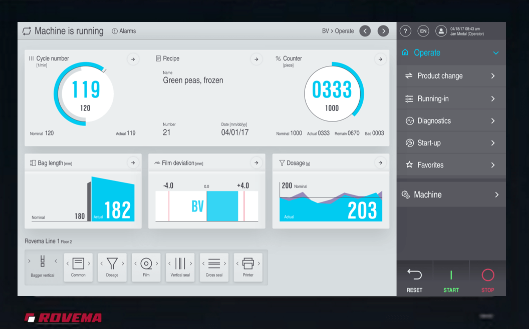
Contact your manufacturer and discuss the issues you are having. When upgrading your servos and controls, you are actually getting a total electrical conversion. This includes the HMI, servos, PLC, gearbox, VFDs and more. Even small items such as relays and terminals are included. These small but important items are included so the entire electrical system will be new with almost zero runtime and no wear. The full upgrade increases the electrical life of the machine.
Compilation of documentation. Both the manufacturer and customer will need to gather and review the information they have on the machine. Drawings, programs, BOM (Bill of Material), and any other forms of documentation are used to review the profile of the machine. The more data you have to accurately describe the machine the better. One reason it is so important is that it will save time on the site visit, which will in turn, save you money.
Site visit. During this visit, the electrical technician will take photos and measurements of items such as the gearing and panel. Video may be compiled along with notes and other information needed specific to that machine. Getting as much information on the site visit and documentation compilation is extremely important. This preparation will decrease the downtime needed to perform the electrical conversion.
BOM: The measurements, lists, and pictures will be used to create a BOM for the upgrade. As this is being produced, the drawings will be developed at the same time. The communication between engineers from the VFFS manufacturer and customer is frequent at this point. Not only do your engineers have knowledge of the machine, but they also have knowledge on how the operators use the machine and any quirks the machine has.
Review of Drawings: You will review and approve the new drawings (and sometimes BOM) with the manufacturer. This is important because it provides another opportunity to clarify any missing or incorrect information. If you have made improvements on the machine yourself, this may not be in the documents the manufacturer has compiled. This is another opportunity to ensure that upgrade is seamless.
Manufacturing of Electrical Panel: After drawings are sent, they are released for manufacturing. The panels are typically built in the manufacturer’s facility, crated up, and then delivered to the plant. Packing and crating is a delicate procedure. The panel is open and needs to be handled with care.
Installation: The upgraded panel and wiring are installed on the VFFS and the firmware is upgraded. The firmware is the software that resides on a specific device and determines how it will communicate with the operating system and other devices.
Powering up of Machine: The machine is turned on and then checked for any issues with voltage or something similar. IP addresses are provided and programs are loaded. Programs are developed for the PLC, HMI, and any other device that may require a program.
IO checks, jogging and troubleshooting: once programs uploaded, IO checks are completed. Sensors are tested, commonly referred to as ‘flagged,’ to detect any issues with power, wiring, or programming. Verification of wiring and accurate movements of the machine are determined. Confirming all parts are physically moving and going in the correct direction will let you know if scaling is off.
Dry cycle: A dry cycle is a run of the machine without film or product. This verifies consistency of motion.
Machine testing with film: The film is threaded through the machine and tested. With the empty bags created, correct heat and motion of the jaws is verified. You want to determine well-formed and sealed bags are consistent instead of sporadic. The process of making a bag should be smooth at this point.
Final troubleshooting. The VFFS is run with film, product, and full testing. An initial test run will start at slower speeds. Once it is determined that bags are perfectly formed, speed will be gradually increased until desired bpm (bags per minute) is reached. Testing will also occur with other application such as printer and gusseting.
The process is complete and final approval of the machine will be provided. Once the installation occurs, expect around 1 week downtime for one machine. Two machines would require 1 ½ weeks as working on them in tandem will save time.
With thoughtful planning, research and preparation, your electrical conversion can be a seamless experience. Please let us know if you have any additional helpful hints or thoughts on upgrading your servos and control panel.

1 min read
The overall efficiency of any form, fill, seal machinery always hinges on the effectiveness of the sealing process. Packaging has many jobs to do-...

When looking at the OEE (Overall Equipment Effectiveness) of your VFFS machine, it is important to know various parts and processes, especially for...