SQUEEZE ROLLERS ALIGNMENT PROCEDURES
SQUEEZE ROLLER ALIGNMENT PROCEDURES – REAR ROLLERS
SQUEEZE ROLLER ALIGNMENT PROCEDURES – FRONT ROLLERS
Squeeze Rollers Alignment Procedures
The squeeze rollers alignment procedure ensures that the front and rear rollers are centered over the sealing jaws and under the filling tube.
This procedure may need to be modified depending on the specific work that needs to be completed and the current alignment of the assemblies.
The squeeze roller alignment is a two-part process. The first part involves aligning the shafts (drawbars) that drive the rear roller assembly. The second part involves positioning the front rollers assembly on its drawbars. Once both parts of the procedure are complete, the squeeze rollers will meet at the center of the sealing jaws and the forming tube when they close.
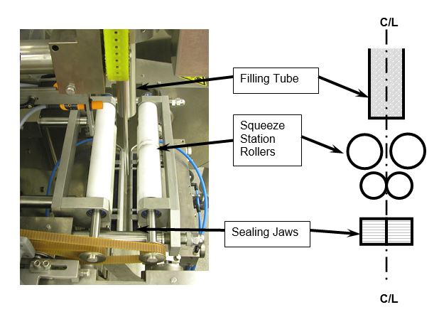
Illustrates how the Sealing Jaws, Squeeze Rollers and Filling Tube should be centered.
Squeeze Roller Alignment Procedures – Rear Rollers
The rear roller alignment procedure positions the drawbars so that they are parallel and extend the same
distance through the machine front plate.
To align the rear roller carrier shafts:
- Jog the horizontal sealing jaws to the closed position (or almost closed position, the optional spring
clamps may prevent the jaws from being closed completely). It is also recommended to have the jaws in
the lower closed position, as this provides additional room between the rollers and the jaws to work on
the assemblies.
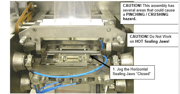
Shows the jaws in the closed position
2. Lock-Out and Tag-Out the machine.
Squeeze Roller Alignment Procedures – Rear Rollers
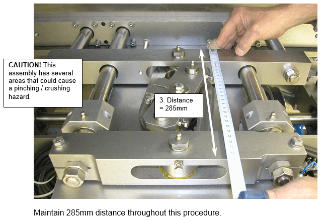
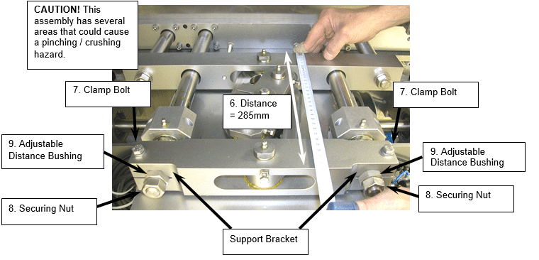
3. Move (push) the squeeze rollers until the distance between the outer edges of the shaft support bracket
is 285mm (#3 Below). The below assembly is located inside the machine housing.
This distance will need to be rechecked several times during this procedure to verify the assembly doesn’t move.
Squeeze Roller Alignment Procedures – Rear Rollers
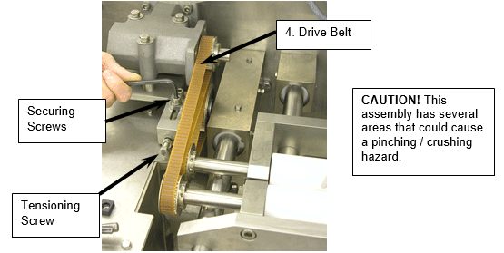
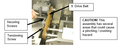
4. Remove the drive belt by loosening the securing screws and the tensioning screw to allow enough slack
to remove the belt (#4 Below).
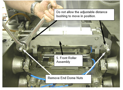
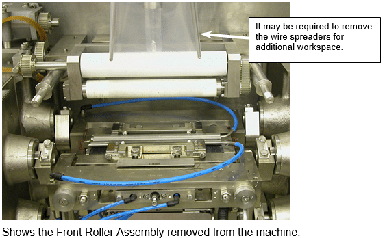
5. Remove the front roller assembly (#5 Below). Remove the two end dome hex nuts and pull off the
assembly.
NOTE: Do not turn the adjustable distance bushing, as this will change the setup location of the front
rollers.
Squeeze Roller Alignment Procedures – Rear Rollers
Squeeze Roller Alignment Procedures – Rear Rollers
6. Recheck the 285mm distance (#6 Below), located inside the machine housing. If it is not 285mm, move
the assembly back to 285mm.
7. Loosen the two bolts that clamp the support bracket to the drawbars (#7 Below).
8. Loosen or remove the two end securing nuts that secure the support bracket to the drawbars (#8
Below). Do not move the adjustable distance bushing while loosening the outer nut as this will change
the set position.
9. Turn both the distance bushings clockwise until they are flush with the surface of the support bracket. (This ensures that the shafts are at an equal distance and parallel.)
Squeeze Roller Alignment Procedures – Rear Rollers
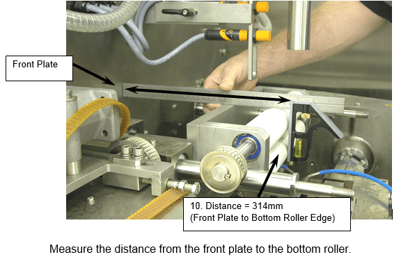
10. Turn, (back out / turn counter clockwise) the distance bushings (#9 Above) an equal amount until the
front edge of the rear roller is 314mm away from the front plate (#10 Below). It is recommended to
make a mark on both adjustable distance bushings (#9 Above) and count the number of turns equally
on both nuts, to ensure that both shafts remain parallel and an equal distance.
This will align the center of the rear rollers directly above the center meeting point of the front and rear
seal jaws.
Recheck the 285mm distance (#6 Above), located inside the machine housing. If this distance has been
changed, move the assembly back to 285mm and repeat procedures #9 & #10.
You may need to make small adjustments and take frequent measurements.
11. Once the distance is correct, clamp the bracket into position by tightening the two bolts (#7 Above).
12. Secure the support bracket in this position with the securing nuts (#8 Above). Do not allow the
adjustable distance bushing to move while tightening as this will change the previous settings.
Squeeze Roller Alignment Procedures – Front Rollers
Use the following procedure to position the front roller assembly. At this point, the bagmaker should
still be locked-out and tagged-out, and, the distance between the internal support brackets should still
be 285mm apart.
To position the front jaw assembly:
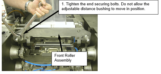
1. Install the front roller assembly. Put the assembly on the shafts and tighten the securing bolts.
NOTE: Do not turn the adjustable distance bushing, as this will change the setup location of the front rollers.
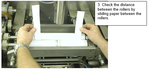
2. Check the distance between the bottom squeeze rollers. Slide a piece of paper or feeler gauge between
the rollers. (The paper should be able to move between the rollers with a only a slight amount of
friction.)
3. Check both sides of the rollers and rotate the rollers as the roller may not be perfectly round after use
during production. If the paper can move between the rollers, with the same amount of friction on both
sides, then the rollers are parallel.
Squeeze Roller Alignment Procedures – Front Rollers
4. If the paper does not slide between the rollers with the same amount of friction on both sides, then
the roller assembly will need to be adjusted.
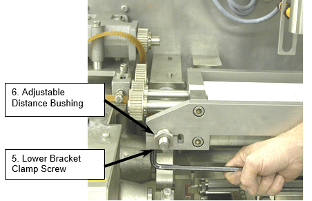
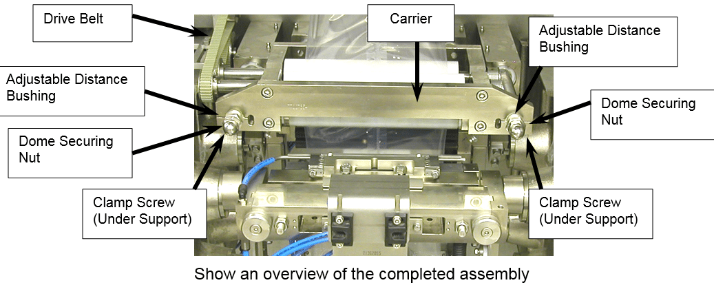
5. Loosen or remove the end dome hex nut and loosen the lower bracket clamp screw (#5 Below). This
may need to be done on one side or both sides depending on the adjustment.
6. Turn the adjustable distance bushing (#6 Below), on the side of the squeeze roller that needs
adjusted.
7. Re-tighten the dome hex nut and check the distance apart with the paper distance test (#3 Above). Repeat making adjustments and measuring as necessary.
8. Once the rollers distance is acceptable, secure the lower securing nut (#5 above) and tighten the end dome hex nut to hold the assembly in position.
9. Reinstall the drive belt (#9 Below). Note: The tension of the belt increases when the rollers are in the open position. Thus, after installation, verify that the tension is not too tight when the rollers are in the open position.
Squeeze Roller Alignment Procedures
10. After the set up is complete, run the machine in Jog Mode to verify correct operation.
------------------------------------------------------------------------
More Rovema Support Options
See Additional Maintenance Articles
Looking for a manual for you Vertical Form Fill and Seal (VFFS) Bagger? Click here!