Jaw Carrier Alignment Procedures – Rear Jaw
The rear carrier shaft alignment procedure positions the draw bars that drive the rear jaw assembly so that they extend the same distance through the machine front plate. Once the shafts are positioned, the front face of the rear jaw body will be the proper distance away from the machine front plate—which centers it under the forming tube.
Steps for setup of VPI-260 and 400
Please note that this needs to be performed only with the Lock Out Tag Out procedure
1) Remove the front jaw carrier.
2) Push the jaws together so you will be able to apply the jig.
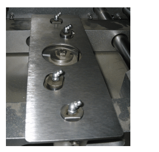
3) Put the jig over top of the bearings.
Please note the correct placement of the bearings. If you have to turn over the plate to fit than the arms are connected wrong and note that the VPI-260 jig and VPI-400 jig are different.
See the picture below
4) Measure the distance from the plate to the front face of the rear jaw body.
See the picture below
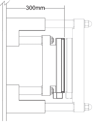
Please note the center line dimensions
Center line Dimensions
VPI-260 = 320 mm from frame
Example Front Plate is 20mm thick so center line will be 320 mm minus 20 mm = 300 center
4) If the dimension of is incorrect the rear jaw bushings need to be adjusted.
See the procedure below

Loosen the two bolts (Item 1) that clamp and hold the bushings from turning in the support bracket.
(Item 2)
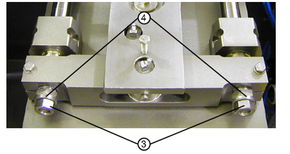
Remove the 2 nuts (Item 3) and washers (Item 4)
Please note when changing the bushing distance that both sides are to be adjusted equally.
The rear carrier shaft alignment procedure positions the draw bars that drive the rear jaw assembly so that they extend the same distance through the machine front plate. Once the shafts are positioned, the front face of the rear jaw body will be 300mm away from the machine front plate—which centers it under the forming tube.
5) Slide the front jaw carrier on to the shafts and push completely on. The front jaw body and the carrier bushings should touch at the same time.
See the picture
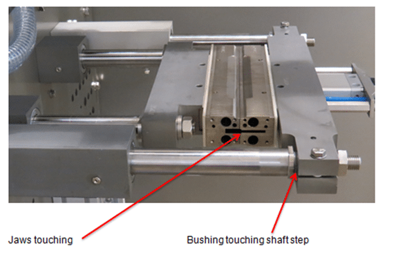
Please note: If the front jaw body touches and the bushings do not than adjust the bushings in.
If the bushings touch and the jaw body does not than adjust the bushings out.
6) Remove the jig and tighten the front jaw carrier.
Once both parts of the procedure are complete, the sealing jaws will meet at the center of the forming tube when they close and apply even pressure across the sealing surfaces.
Horizontal Sealing Jaws Alignment
Checking the alignment of the horizontal sealing jaws.
There are two types of paper that may be used for the Paper Alignment Test (Type A or B, as described below).
Type A Paper: Pencil Carbon Paper is used on jaws at room temperature.
Type B Paper: TP Paper (Temperature-Pressure) is used on hot jaws (approximately 200°-300°F). The acceptable temperature is specified by the manufacture of the paper.
1. Obtain the paper (Carbon Paper or TP Paper0 and tape.
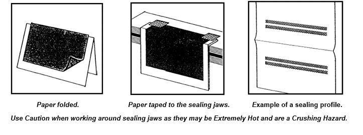
2. If using carbon paper, place the coated side of carbon paper on the white paper and fold it, as shown below. If using TP Paperâ, a white piece of paper is not required.
3. Place the paper between the sealing jaws and fasten them to the front jaw using tape. As shown below.
4. Close the protective doors.
5. Access the JOG MENU on the HMI of the machine and close the horizontal jaws in the jogging mode.
6. Open the horizontal jaws, open the protective doors, lift off the paper and inspect the profile prints on the paper.
7. If adjustments are required, refer to the following instructions.
Aligning the Horizontal Jaws
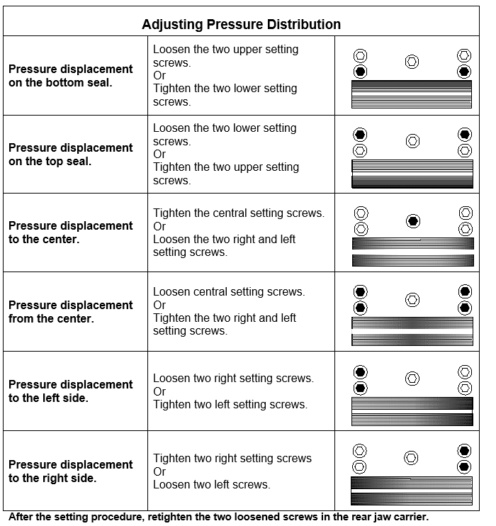
How to Adjust the Pressure Distribution
Note: If satisfactory results were not obtained on the paper alignment test, adjust the pressure distribution by following these procedures.
1. Allow the jaws to cool.
2. Close the horizontal jaws until they are touching each other.
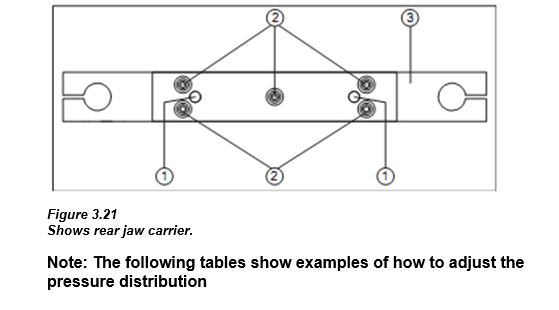
3. Loosen both screws (#1) in the rear jaw carrier. The front jaw assembly remains unchanged.
4. To obtain an equal pressure distribution, tighten or loosen the adjusting screws (#2), as required,
per the results from the carbon paper test.
Repeat the carbon paper test. (it may be necessary to repeat these steps to obtain the desired results.)
Remove your lock and power up the machine. Home the jaws and run empty bags.
------------------------------------------------------------------------
More Rovema Support Options
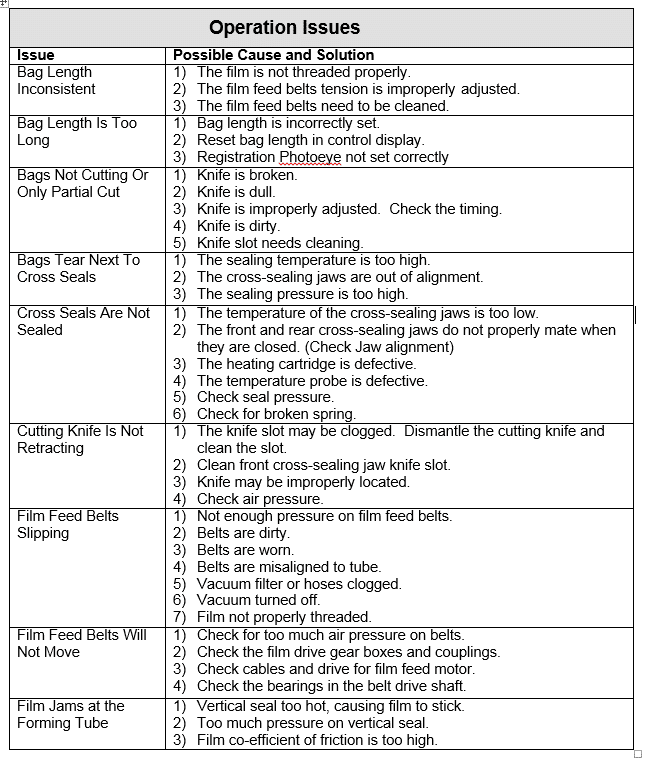
See Additional Mechanical Issues
Looking for a manual for you Vertical Form Fill and Seal (VFFS) Bagger? Click here!